Using QEMU instead of cross compiling for raspberry pi

I recently had to compile c++ code for the Raspberry pi and bumped into some issues because of the complexity of the code. There are at least four ways to build a binary:

  1. Compile the code on a Raspberry pi using a native compiler (a compiler that runs on arm and produces arm binaries)
  2. Cross-compile it on a powerful machine using a cross-compiled toolchain (runs on your normal x86_64 machine and produces arm binaries)
  3. Run a native arm compiler thorugh QEMU on a powerful x86_64 machine - this is what we’re going to do
  4. Run a native arm compiler by emulating the whole Raspberry pi system including the kernel

Compiling on the Raspberry pi itself works well if the code is small and doesn’t have a ton of heavy dependencies (e.g. boost). The problem one might run in to is that the resources of the poor Raspberry pi run out, i.e. the memory isn’t enough and/or it simply takes too long time to compile since the cpu is weak.

Cross-compiling is the proper solution but it requires a bit of preparation and might take a lot of time to set up in case the toolchain has to be built (this is when a prebuilt toolchain is nice to have). You can read the Hackaday writeup on how this goes here.

Running the native arm compiler through QEMU maybe seems slow and weird but it could save some time. It did for me which is why I wrote this post.

The fourth method should also be possible but I haven’t tried it and it seems complicated and even slower.

Getting a build environment up and running

The following guide assumes you are running Archlinux with pacaur on an x86_64 machine and that you’ve got root. We will target the ARMv6 Raspberry Pi, i.e. Raspberry pi, zero and zero w. Use this guide with caution since we’re going to be playing with mounts that might harm your system.

Download the latest Archlinux distribution for the Raspberry pi.

Extract the archive and cd into it: (If you don’t have bsdtar, install the libarchive package)

1
2
3
$ mkdir -p arch-pi
$ bsdtar -xpf ArchLinuxARM-rpi-latest.tar.gz -C arch-pi
$ cd arch-pi

If you see error messages like ./var/db/: Failed to set file flags it means that your file system doesn’t support the flags, but don’t worry about that. This might happen in case you’re running btrfs.

Install qemu-user-static and binfmt-support from AUR:

1
$ pacaur -S qemu-user-static binfmt-support

Now we will enable the magic of binfmt-support. What it does is that it will make use of a kernel feature to use an interpreter when execuring ARM binaries and run it through QEMU instead. Read more here.

1
2
$ sudo update-binfmts --enable
$ update-binfmts --display

The second command will show you which ELF headers it that will be intercepted. Ensure that you can see qemu-arm (enabled) in the list.

Copy qemu-arm-static to ./usr/bin/:

1
$ sudo cp $(which qemu-arm-static) ./usr/bin/

In order to be able to run pacman and other tools, we have to trick the environment into thinking that it’s running a full OS. We do this by mounting in some special paths. Note that this gives the emulated Archlinux environment control of your host machine. But since we’re only building code, this should be fine.

1
2
3
4
5
6
7
8
9
10
11
12
13
# Mount the /proc file system
$ sudo mount -t proc proc proc
# Hack: Replace ./etc/mtab with a copy of your mounts
$ unlink ./etc/mtab
$ cat /proc/self/mounts > ./etc/mtab
# Hack: Hard code a nameserver in ./etc/resolv.conf since systemd isn't running
$ unlink ./etc/resolv.conf
$ echo "nameserver 8.8.8.8" > ./etc/resolv.conf
# Sometimes it's nice to have /dev/null. If needed, mount it in:
$ touch ./dev/null && sudo mount -o bind /dev/null ./dev/null

Chroot into the file system and start executing ARM binaries:

1
2
3
$ sudo chroot . ./bin/bash
[root@bacon ~]# uname -a
Linux bacon 4.10.13-1-ARCH #1 SMP PREEMPT Thu Apr 27 12:15:09 CEST 2017 armv7l GNU/Linux

Notice armv7l, it means we’re running commands through QEMU.

Now it’s time to install the tools you need to build your code. In my case I needed base-devel and cmake. % illustrates that we’re in the chroot environment.

1
2
3
# Update, then install the packages
% pacman -Syyu
% pacman -S base-devel cmake

The environment should be ready to build your code now. Don’t forget to use all of your cores when building.

Problems

Some tools might expect /dev/fd/ to be set up properly. This can be solved with an epic hack.

1
2
# Run this inside the chroot
% ln -s /proc/self/fd /dev/fd

I had some problems accessing https resources, not sure why. If someone has a clue please let me know (I just get curl: (35) SSL connect error and similar errors.)

Headless raspberry pi (for reals)

If you want to install and interact with a raspberry pi using only a USB cable and nothing else (no UART hardware, no physical keybord, hdmi-screen, wifi, network cable etc), this guide is for you. We will set up wifi and enable ssh while we’re at it just because we can.

We are going to:

  • Download and install the latest raspbian-jessie-lite on an SD-card
  • Configure the pi to act as a USB serial device
  • Configure wpa_supplicant with your wifi AP’s credentials
  • Create symlinks to enable systemd services on boot (wpa_supplicant, ttyGS0 and ssh)

This guide has only been tested on a Raspberry Pi Zero W, but should work fine on other Pis.

Download and transfer raspbian-jessie-light to an sdcard (assuming /dev/mmcblk0 here)

1
2
3
4
$ wget https://downloads.raspberrypi.org/raspbian_lite_latest
$ unzip raspbian_lite_latest
$ sudo dd if=2017-04-10-raspbian-jessie-lite.img of=/dev/mmcblk0 status=progress bs=1M
$ sync

Mount the boot partition

1
2
$ mkdir boot
$ sudo mount /dev/mmcblk0p1 boot

Add the following line in the end of boot/config.txt to enable the DWC2 USB driver (this enables USB gadgets):

1
dtoverlay=dwc2

Add modules-load=dwc2,g_serial after rootwait in boot/cmdline.txt

1
2
# Your cmdline.txt should look something like this (but might differ and that's fine)
dwc_otg.lpm_enable=0 console=serial0,115200 console=tty1 root=/dev/mmcblk0p2 rootfstype=ext4 elevator=deadline fsck.repair=yes rootwait modules-load=dwc2,g_serial quiet init=/usr/lib/raspi-config/init_resize.sh

Let’s configure the root filesystem.

1
2
3
4
5
6
7
8
9
10
11
12
13
14
15
16
17
18
19
20
21
22
23
24
25
26
27
28
29
30
31
# Mount the root partition
$ mkdir root
$ sudo mount /dev/mmcblk0p2 root
$ cd root
# Configure your wifi credentials by editing /etc/wpa_supplicant/wpa_supplicant.conf
$ sudo vim etc/wpa_supplicant/wpa_supplicant.conf
ctrl_interface=DIR=/var/run/wpa_supplicant GROUP=netdev
update_config=1
network={
ssid="Your SSID"
psk="Password"
}
# Save and exit
# Fake systemctl enable wpa_supplicant.service
$ cd ./etc/systemd/system/multi-user.target.wants
$ sudo ln -s ../../../../lib/systemd/system/wpa_supplicant.service
# Fake systemctl enable ssh.service
$ sudo ln -s ../../../../lib/systemd/system/ssh.service
# Fake systemctl enable getty@ttyGS0.service
$ cd ../getty.target.wants
$ sudo ln -s /lib/systemd/system/getty@.service getty@ttyGS0.service
# Done! Sync and unmount
$ cd ../../../../..; sync; sudo umount boot root

Remove the sd-card and insert it in your Pi, connect a USB cable in the “USB Data port”, then connect it to your computer. Run journalctl -f on your host machine to see what happens then the Pi boots. After a while, you will probably end up seeing

1
May 06 21:04:54 bacon kernel: cdc_acm 1-2:2.0: ttyACM0: USB ACM device

Go ahead now and connect to the device using screen /dev/ttyACM0 115200 and interact with your raspi. In case you’ve never used screen before: exit using <Ctrl>-a d.

1
2
pi@raspberrypi:~$ uname -a
Linux raspberrypi 4.4.50+ #970 Mon Feb 20 19:12:50 GMT 2017 armv6l GNU/Linux

While writing this guide I used qemu-arm-static in order to enable the systemd services. This turned out to be really messy (segfault in strange places etc). If you want to try this approach, feel free to change the symlink steps above to the following:

1
2
3
4
5
6
7
8
9
10
11
12
13
14
15
16
17
18
19
20
# Install qemu-user-static. On archlinux with AUR:
$ pacaur -S qemu-user-static
# Ubuntu:
$ sudo apt-get install qemu-user-static
# Copy qemu-arm-static to the root filesystem
$ sudo cp $(which qemu-arm-static) ./usr/bin/
# Enter the pi's root filesystem by running the local bash(dash) using `qemu-arm-static`
$ sudo chroot . ./usr/bin/qemu-arm-static /bin/bash
# We are now in the mounted root filesystem.
# Enable wpa_supplicant so that it runs on boot
% qemu-arm-static /bin/systemctl enable wpa_supplicant.service
# Enable the USB TTY service
% qemu-arm-static /bin/systemctl enable getty@ttyGS0.service
# Enable SSH (this might result in a segfault...)
% qemu-arm-static /bin/systemctl enable ssh.service

More reading

Adafruit’s article on how to enable the USB gadgets
CONFIG_USB_DWC2: DesignWare USB2 DRD Core Support
Linux-USB Gadget API Framework

Morse generator without clicks

I just made a lousy morse signal generator in javascript. The idea is to develop this further and implement BPSK31 and other things, but morse is a start.

Code can be found here, and a demo is here.

NFC Antenna Generator

I am currently designing a board with a PCB trace NFC-antenna and spent some time trying to figure out a good shape of the antenna.

ST has a nice tool in their eDesignSuite to calculate the inductance based on the size and number of turns. But if you end up with a lot of turns it can be quite boring to draw the antenna yourself, so I made a tool for it. Could have done it in any language but ended up using javascript since it can be used directly in the browser.

Behold, the NFC Antenna Generator. It generates a footprint in any resolution that can easily be imported in KiCad or similar. Enjoy!

Sample antenna

FreeMate

Club Mate is an awesome beverage. Here’s how to do it yourself.

HOWTO FreeMate

DEPENDENCIES

  • Yerba Mate Tea
  • Sugar, preferrably dissolved in water
  • Lemon Juice
  • Carbonated Water

BUILDING

SuperStrong Mate Tea (1 liter):

  • Boil 1 liter water.
  • Add 5 tablespoons of Yerba Mate Tea.
  • Let it sit for at least 7 minutes.
  • Filter it through a coffee filter. This makes it less cloudy.
  • Let it cool down and finally put it in the fridge.

Dissolved sugar in water:

  • Boil a small amount of water (e.g. 2dl)
  • Add sugar until the solution becomes a little bit thicker than water.
  • Don’t add too much sugar, then it will not be easy to use later.

INSTALLING

  • For each serving of FreeMate:
    • 20% SuperStrong Mate Tea
    • Add as much sugar as required by your system, but don’t take too much
    • Add a few dashes of Lemon Juice
    • Mix it well
    • Add Carbonated Water
    • Mix carefully
    • Ready for consumption

TESTING

  • Every now and then, compare your FreeMate installation with a Club Mate. This will let you realize what a fantastic beverage you have created.

COPYING

“THE BEER/MATE-WARE LICENSE”:
konrad@xil.se wrote this file. As long as you retain this notice you
can do whatever you want with this stuff. If we meet some day, and you think
this stuff is worth it, you can buy us a ( > 0 ) beer/mate in return - Konrad Beckmann

Bit-banging two pins simultaneously on ESP8266

I’m currently building an 8 x 144 LED panel using ws2812 LED-strips. That results in 27648 bits per frame. With an optimal driver it takes a constant time of 34.56ms per frame (27648 bits * 1.25us per bit). Even if I spend every single clock cycle pushing pixels, I can only reach 29 fps. But I want to do other stuff with my ESP8266 as well.

A solution to get higher frame rate is to simply reduce the number of LEDs to control via the same data pin and use multiple pins instead. The tricky part is to get the timing right.

Since the ESP8266 is quite fast it is possible to use two pins and get the timing right.

Here’s the code that I came up with and it works pretty well. I get my high framerate and it’s really smooth. Full code here.

1
2
3
4
5
6
7
8
9
10
11
12
13
14
15
16
17
18
19
20
21
22
23
24
25
26
27
28
29
30
31
32
33
34
35
36
37
38
39
40
41
42
43
44
45
46
47
48
49
50
51
52
53
54
55
56
57
58
59
60
61
62
63
64
65
static void ICACHE_RAM_ATTR __attribute__((optimize("O2"))) ws2812_writedual(
uint8_t pin_a, uint8_t pin_b, uint8_t *pixels, uint32_t num_bytes) {
uint8_t *p1, *p2, *end, pix_a, pix_b, mask;
uint32_t t, t0h, t1h, t01h, ttot, c, start_time;
uint32_t pin_mask_a, pin_mask_b, pin_mask_ab, bits;
pin_mask_a = 1 << pin_a;
pin_mask_b = 1 << pin_b;
pin_mask_ab = pin_mask_a | pin_mask_b;
p1 = pixels;
p2 = pixels + num_bytes / 2;
end = p1 + num_bytes / 2;
pix_a = *p1++;
pix_b = *p2++;
mask = 0x80;
start_time = _getCycleCount();
t0h = (1000 * system_get_cpu_freq()) / 2857; // 0.35us (spec=0.35 +- 0.15)
t1h = (1000 * system_get_cpu_freq()) / 1428; // 0.70us (spec=0.70 +- 0.15)
ttot = (1000 * system_get_cpu_freq()) / 800; // 1.25us (MUST be >= 1.25)
t01h = t1h + t0h; // Time to wait when having different bits
while (true) {
while (((c = _getCycleCount()) - start_time) < ttot); // Wait for the previous bit to finish
GPIO_REG_WRITE(GPIO_OUT_W1TS_ADDRESS, pin_mask_ab); // Set pin a and b high
start_time = c;
if (pix_a & mask) {
if (pix_b & mask) {
// 11;
while (((c = _getCycleCount()) - start_time) < t1h); // Wait high duration
GPIO_REG_WRITE(GPIO_OUT_W1TC_ADDRESS, pin_mask_ab); // Set pin a and b low
} else {
// 10;
while (((c = _getCycleCount()) - start_time) < t0h); // Wait high duration
GPIO_REG_WRITE(GPIO_OUT_W1TC_ADDRESS, pin_mask_b); // Set pin_b low
while (((c = _getCycleCount()) - start_time) < t01h); // Wait remaining time
GPIO_REG_WRITE(GPIO_OUT_W1TC_ADDRESS, pin_mask_a); // Set pin_a low
}
} else {
if (pix_b & mask) {
// 01;
while (((c = _getCycleCount()) - start_time) < t0h); // Wait high duration
GPIO_REG_WRITE(GPIO_OUT_W1TC_ADDRESS, pin_mask_a); // Set pin_a low
while (((c = _getCycleCount()) - start_time) < t01h); // Wait remaining time
GPIO_REG_WRITE(GPIO_OUT_W1TC_ADDRESS, pin_mask_b); // Set pin_b low
} else {
// 00;
while (((c = _getCycleCount()) - start_time) < t0h); // Wait high duration
GPIO_REG_WRITE(GPIO_OUT_W1TC_ADDRESS, pin_mask_ab); // Set pin a and b low
}
}
if (!(mask >>= 1)) {
if (p1 >= end) {
break;
}
pix_a = *p1++;
pix_b = *p2++;
mask = 0x80;
}
}
}

The ws2812 uses a single data pin. Data is sent by sending pulses with either a short or long duty cycle. A 0 is sent with a shorter high, a 1 is sent with a longer. The period must be at least 1.25us long.

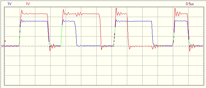
Looking at the signals with a scope shows that the timings are good enough.

Two channels

Tinkering with the ESP8266

Tinkering with the ESP8266

A friend of mine showed me the ESP8266 and I just had to play with it. It’s sold as a serial-to-wifi module to Arduino but the firmware can be changed to do more. It’s also really cheap, about $2.20 from Aliexpress.

We flashed NodeMCU onto it and wrote some Lua code to connect to a wifi-AP and access a webpage. And it worked, most of the times at least. The stability and reliability isn’t really 100% currently, but hopefully it will be improved over time.

Connecting it

I haven’t got all the tools and power supplies yet so we had to do dirty hacks to get it to work. In order to use the chip, 3.3V and ground need to be connected to two pins each. A proper power supply and a bredboard would’ve done things easier but there’s always a way if you don’t have it.

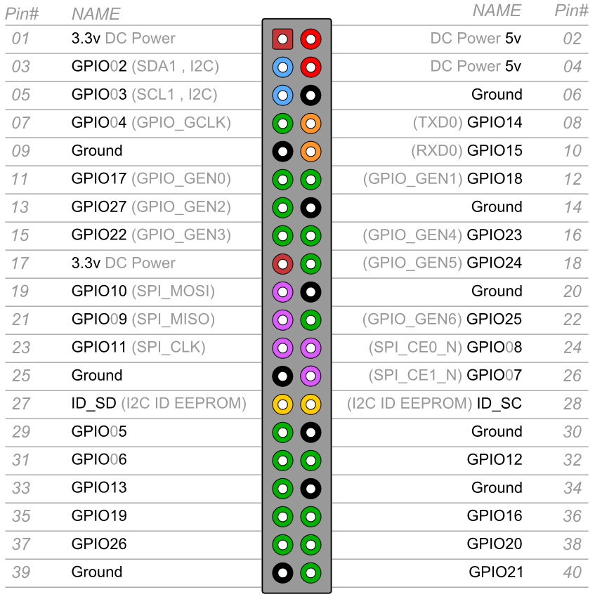
We found a dusty Raspberry Pi B and just used its 3.3 volt and ground pins. Good for us that there are multiple connectors.

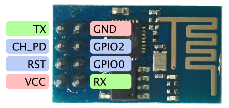
In order to use the chip, the following pins need to be connected:

+3.3V  => VCC
+3.3V  => CH_PD
GND    => GND
GND    => GPIO0 When flashing the firmware

A USB-to-serial is also needed. Make sure that it uses 3.3V. I used a PL2303HX, it’s pretty cheap. Connect it:

GND => GND
RX  => TX
TX  => RX
+5V => don't connect this :)

Code to access the web

After flashing NodeMCU, it’s time for some Lua scripting. It’s possible to just connect to the serial interface and just write code, but it gets really frustrating when your code grows, obviously.

There’s an IDE called esplorer that helps you out. It’s pretty basic and written in java, but it gets the job done. There’s also an AUR package for it so you can install it quickly if you run Arch.

1
2
3
4
5
6
7
8
9
10
11
12
13
14
15
16
17
18
19
20
21
22
23
24
25
26
27
28
29
30
31
32
33
34
35
36
37
38
39
40
41
42
-- Connect to a wifi-ap
wifi.setmode(wifi.STATION)
wifi.sta.config("your-ssid", "password")
-- Set a timer with 500ms delay and check if we've got an IP-address
tmr.alarm(0, 500, 1, function()
if wifi.sta.getip() == nil then
print("No ip yet")
else
print("Got ip: " .. wifi.sta.getip())
tmr.stop(0)
reg_gpio()
end
end)
-- Register an interrupt on GPIO pin 3 (it's called GPIO0 on the board)
-- "both" is used because it seems to work better than simply "up".
-- This means that the callback is called whenever the pin goes high or low.
-- Not sure if it's because of a bug in the firmware or I just had bad luck
-- when testing.
function reg_gpio()
gpio.mode(3, gpio.INT)
gpio.trig(3, "both", function(level)
print("both: 3 " .. level)
if level == 1 then
http_get("192.168.0.1", 80, "192.168.0.1", "/")
end
end)
end
-- A simple HTTP GET call. Not optimal but works.
function http_get(host_addr, port, hostname, path)
print("http_get()")
sk=net.createConnection(net.TCP, 0)
sk:on("receive", function(sck, c) print(c) end )
sk:connect(port, host_addr)
request = "GET " .. path .. " HTTP/1.1\r\n" ..
"Host: " .. hostname .. "\r\n" ..
"Connection: close\r\nAccept: */*\r\n\r\n"
print(request)
sk:send(request)
end

My code works most of the time but not always. It’s probably because the firmware is still a bit buggy, but hopefully it will improve.

Pinout reference

Here are the pinout configurations for reference.

ESP8266

Pinout configuration of ESP8266

Raspberry PI B+. A and B only have 26 pins, they are the same. Source

Pinout configuration of ESP8266

Hello hexo.io

It was finally time to setup a blog and I wanted something statically generated. hexo.io seemed nice so that’s what I’m using. Found a nice installation guide so setting everything up went pretty fast. Really like it so far.