Bit-banging two pins simultaneously on ESP8266

I’m currently building an 8 x 144 LED panel using ws2812 LED-strips. That results in 27648 bits per frame. With an optimal driver it takes a constant time of 34.56ms per frame (27648 bits * 1.25us per bit). Even if I spend every single clock cycle pushing pixels, I can only reach 29 fps. But I want to do other stuff with my ESP8266 as well.

A solution to get higher frame rate is to simply reduce the number of LEDs to control via the same data pin and use multiple pins instead. The tricky part is to get the timing right.

Since the ESP8266 is quite fast it is possible to use two pins and get the timing right.

Here’s the code that I came up with and it works pretty well. I get my high framerate and it’s really smooth. Full code here.

1
2
3
4
5
6
7
8
9
10
11
12
13
14
15
16
17
18
19
20
21
22
23
24
25
26
27
28
29
30
31
32
33
34
35
36
37
38
39
40
41
42
43
44
45
46
47
48
49
50
51
52
53
54
55
56
57
58
59
60
61
62
63
64
65
static void ICACHE_RAM_ATTR __attribute__((optimize("O2"))) ws2812_writedual(
uint8_t pin_a, uint8_t pin_b, uint8_t *pixels, uint32_t num_bytes) {
uint8_t *p1, *p2, *end, pix_a, pix_b, mask;
uint32_t t, t0h, t1h, t01h, ttot, c, start_time;
uint32_t pin_mask_a, pin_mask_b, pin_mask_ab, bits;
pin_mask_a = 1 << pin_a;
pin_mask_b = 1 << pin_b;
pin_mask_ab = pin_mask_a | pin_mask_b;
p1 = pixels;
p2 = pixels + num_bytes / 2;
end = p1 + num_bytes / 2;
pix_a = *p1++;
pix_b = *p2++;
mask = 0x80;
start_time = _getCycleCount();
t0h = (1000 * system_get_cpu_freq()) / 2857; // 0.35us (spec=0.35 +- 0.15)
t1h = (1000 * system_get_cpu_freq()) / 1428; // 0.70us (spec=0.70 +- 0.15)
ttot = (1000 * system_get_cpu_freq()) / 800; // 1.25us (MUST be >= 1.25)
t01h = t1h + t0h; // Time to wait when having different bits
while (true) {
while (((c = _getCycleCount()) - start_time) < ttot); // Wait for the previous bit to finish
GPIO_REG_WRITE(GPIO_OUT_W1TS_ADDRESS, pin_mask_ab); // Set pin a and b high
start_time = c;
if (pix_a & mask) {
if (pix_b & mask) {
// 11;
while (((c = _getCycleCount()) - start_time) < t1h); // Wait high duration
GPIO_REG_WRITE(GPIO_OUT_W1TC_ADDRESS, pin_mask_ab); // Set pin a and b low
} else {
// 10;
while (((c = _getCycleCount()) - start_time) < t0h); // Wait high duration
GPIO_REG_WRITE(GPIO_OUT_W1TC_ADDRESS, pin_mask_b); // Set pin_b low
while (((c = _getCycleCount()) - start_time) < t01h); // Wait remaining time
GPIO_REG_WRITE(GPIO_OUT_W1TC_ADDRESS, pin_mask_a); // Set pin_a low
}
} else {
if (pix_b & mask) {
// 01;
while (((c = _getCycleCount()) - start_time) < t0h); // Wait high duration
GPIO_REG_WRITE(GPIO_OUT_W1TC_ADDRESS, pin_mask_a); // Set pin_a low
while (((c = _getCycleCount()) - start_time) < t01h); // Wait remaining time
GPIO_REG_WRITE(GPIO_OUT_W1TC_ADDRESS, pin_mask_b); // Set pin_b low
} else {
// 00;
while (((c = _getCycleCount()) - start_time) < t0h); // Wait high duration
GPIO_REG_WRITE(GPIO_OUT_W1TC_ADDRESS, pin_mask_ab); // Set pin a and b low
}
}
if (!(mask >>= 1)) {
if (p1 >= end) {
break;
}
pix_a = *p1++;
pix_b = *p2++;
mask = 0x80;
}
}
}

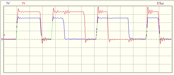
The ws2812 uses a single data pin. Data is sent by sending pulses with either a short or long duty cycle. A 0 is sent with a shorter high, a 1 is sent with a longer. The period must be at least 1.25us long.

Looking at the signals with a scope shows that the timings are good enough.

Two channels